Operation of Machine

5. Size Adjustments & lables
1. Size Adjustments & lables
1.1 Size Change-General
This section is intended to guide the operator through the steps necessary to make the changes required to set up the 16835 Naturelle LLC Case packer for toothpaste packing line no 1.
It takes the form of a list of locations on the machine where changes need to be made. Instructions for each location describe what is being changed and how to make the change. The value of each setting is provided on the operator screen.
After the changeover, the machine must perform the dry cycle (dry run) testing. (Refer the HMI screens manual.)
25
17
14
To make a recipe change:
-
Ensure that the machine is in a safe state, i.e., emergency stopped.
-
On the operator screen, select the desired recipe. This will automatically make changes to the non-Operator adjustable settings of the machine, i.e., Conveyor Speeds, etc.
-
On the Operator Screen, select the Recipe Settings Screen, which corresponds to the chosen recipe. Each adjustment location is numbered on the screen and corresponds to its location on the machine. The location on the machine is highlighted by a Change Part label with the location number on it.
4. Refer to the Size Change Sequence Chart '16835 Size Change List' and adjust the machine assemblies in the order detailed to the value listed on the Recipe Settings Screen.
5. Use the correct carton for the recipe.


15
23
22
18
2. Adjustment locations
2.1 LOCATION 14: Magazine & Picture Farme Assembly
1. Size change location 1401: Rotate the hex nut using a ratchet to adjust the shipper to the required height, referring to the counter display. Once the adjustment is complete, use the handle to lock the counter

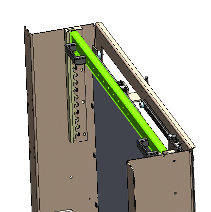
2. Size change location 1402: Partially unscrew the knobs (refer to the image highlighted in green below). Adjust the plates using a scale to achieve the required width for the respective carton by using the Handle, then tighten the knobs.

3. Size change location 1403: Adjust the plates using a scale to achieve the required Height for the respective carton by using the Handle (refer to the image highlighted in green below).
3. LOCATION 15: Bottom Flap Floding
1. Size change location 1502 : Rotate the hex nut using a ratchet to adjust the shipper to the required width, referring to the counter display as per SKU. Once the adjustment is complete, use the handle to lock the counter adjust.

2. Size change location 1503 : Rotate the Wheel to adjust the shipper to the required width, referring to the counter display as per SKU. Once the adjustment is complete, use the handle to lock the counter adjust.

3. Size change location 1504: Rotate the Wheel to adjust the shipper to the required bottom tapping width, referring to the counter display as per SKU. Set the width according to the shipper size or dimension. Once the required width is achieved, use the handle to lock the counter adjustment securely.
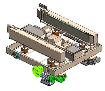
3. Size change location 1505: Rotate the Wheel to adjust the shipper to the required top guide height, referring to the counter display as per SKU. Set the height according to the shipper size or dimension. Once the required height is achieved, use the handle to lock the counter adjustment securely.

4. Size change location 1506: Partially unscrew the knobs (refer to the image highlighted in green below). Adjust the cup plates using the handle and set them to the required width for the respective carton, referring to the scale for accuracy. Once the correct width is achieved, tighten the knobs securely.

4. Adjustment locations
4.1 LOCATION 17: Main Drive & Hopper Assembly
1. Size change location 1701: Loosen the hopper mounting bolts slightly using an Wheel Adjust the hopper vertically according to the sipper height specified for the SKU, using the scale and counter display to set the correct height. Once the required height is achieved, securely tighten the bolts to lock the hopper in position. (refer to the image highlighted in green).

2. Size change location 1702: Partially unscrew the adjustment knobs (refer to the image highlighted in green below). Adjust the hopper flap according to the product length and width, using the knob scale for accurate setting. Once the correct position is reached, securely retighten the knobs to lock the flap in place.

3. Size change location 1703: Rotate the circular knobs partially (refer to the image highlighted in green below). Adjust the plates using the scale to set the required width for the respective carton according to the SKU/shipper size. Once the correct width is achieved, lock the knobs in position.

5. Adjustment locations
5.1 LOCATION 23: Collation Unit
1. Size change location 1701: Slightly loosen the Wheel (refer to the image highlighted in green). Adjust the hopper width on the collation table according to the product size matrix, setting the correct width using the counter. Once the required width is achieved, secure the hopper in position.

2. Size change location Arm Plate No 1 (2302): Adjust the support plate to the required height as per the SKU or product specification. Select the support plate accordingly. Support Plate 1 is fixed and cannot be adjusted. Once the correct support plate is selected and positioned, use the handle to lock it securely in place.

3. Size change location Arm Plate No 2 (2302 ): Adjust the arm plate to the required position as per the SKU or product specification. Once the correct position is achieved, use the handle to lock the arm plate securely in place. Arm Plate 1 is fixed and cannot be adjusted

6 LOCATION 25: Matrix Pick & Place Robot Pick Head
1. Size change location 2501: Partially unscrew the clamp and change the Pick head side plates according to 220 mm
25040.A


25037.A
2. Size change location 2502: Partially unscrew the clamp and change the Pick head side plates according to 280 mm
25037.B


25040.B
3. Size change location 2503: Partially unscrew the clamp and change the Pick head side plates according to 400 mm
25040.C


25037.C
7. Adjustment locations
7.1 LOCATION 18: Infeed Conveyor Assembly
1. Size change location 1801: Partially unscrew the knobs (refer to the image highlighted in green below). Adjust the cylinder position to set the stopping point of the bundle according to the required SKU. Use the handle to move the cylinder vertically, referring to the scale if provided. Once properly aligned in both directions, tighten the knobs securely.

2. Size change location 1802: Partially unscrew the knobs (refer to the image highlighted in green below). Adjust the cylinder position to set the stopping point of the bundle as per the width of the SKU or product. Use the handle to move the cylinder to the required position, referring to the scale if provided. Once correctly set, tighten the knobs securely.
3. Size change location 1803 RH : Partially unscrew the knobs (refer to the image highlighted in green below). Adjust the guide position to set the stopping point of the bundle as per the width of the product or SKU. Use the handle to move the RH guide to the required position, referring to the scale if provided. Once correctly aligned, tighten the knobs securely.

3. Size change location 1803 LH : Partially unscrew the knobs (refer to the image highlighted in green below). Adjust the guide position to set the stopping point of the bundle as per the width of the product or SKU. Use the handle to move the LH guide to the required position, referring to the scale if provided. Once correctly aligned, tighten the knobs securely.

4. Size change location 1804 : Loosen the knobs (refer to the image highlighted in green below). Position the vacuum cup according to the width or size of the product/SKU. Use the handle to slide the vacuum cup into the correct location, checking the scale if available. Once the desired position is reached, firmly tighten the knobs.

5. Size change location 1805 : Loosen the knobs (refer to the image highlighted in green below). Position the vacuum cup according to the width or size of the product/SKU. Use the handle to slide the vacuum cup into the correct location, checking the scale if available. Once the desired position is reached, firmly tighten the knobs.

6. Size change location 1806: Use the adjustment knob to move the assembly horizontally according to the product size or SKU. Move the tilting assembly to the required position. Once aligned correctly, use the handle to lock it securely in place.

7. Size change location 1807: Partially loosen the knob (refer to the image highlighted in green below) and adjust the sensor using the scale knob according to the height of the product bundle. Move the sensor carefully until it aligns with the required height. Once correctly positioned, tighten the knob securely.

8. Adjustment locations
8.1 LOCATION 22: Top Tapping
1. Size change location 2201: Rotate the hex nut using a ratchet to adjust the shipper to the required height according to the specified shipper size, referring to the scale display (see red circle). Once the adjustment is complete, turn the knob (indicated in the image circle) to lock the scale securely.

2. Size change location 2202: Partially unscrew the green knobs to allow the side guides to move, use the handle and scale to adjust the plates to the required carton width, and then tighten the knobs to lock the setting securely.

3. Size change location 2203: Adjust the sensor along the scale to match the required shipper length, then turn the knob shown in the image circle to lock the sensor securely in position.