Operation of Machine

2. Safety Assessment
Project Number
Client
Company
Revision
16808
Bector Automation RML India Pvt. Ltd.
0
Lupin Limited
Introduction to General Safety:
Where appropriate, it is intended that this equipment complies by the guidelines presented in
-
AS4024 - Safety of Machinery [1]
-
BS EN415-7:2006 - Safety of Packaging Machinery [2]
-
ISO 13849:2006 Safety-Related Parts [3]
-
and/or IEC 62061 Safety of Machinery [4]
The supplied Bottle Case Packer (16808), installed at Lupin Limited, Nagpur, is a fully automatic packaging system incorporating advanced servo motion control, pneumatic systems, and robotic automation through a Fanuc Robot 710iD/50M. The machine is designed for high-speed, accurate shrink-bundle packing operations within a pharmaceutical manufacturing environment.
With the exception of the conveyor sections, operators and maintenance personnel are not required to access moving or hazardous machine components during normal operation. Access to such areas is only necessary when the machine has been brought to a fully de-energized and safe state for maintenance, inspection, or troubleshooting activities. Accordingly, from a machine safety and guarding perspective, the equipment is designed and treated as a single integrated safety cell.
The guarding concept comprises fixed perimeter fencing that encloses all hazardous areas of the machine. Controlled access to these areas is provided through strategically located interlocked guard doors, enabling safe intervention when required for maintenance and fault recovery.
In addition to the physical guarding system, the machine is equipped with multiple functional safety measures, including interlocked guard doors, a safety PLC, and emergency stop (E-stop) circuits. Activation of any safety device—such as opening an interlocked guard door or pressing an emergency stop pushbutton—immediately initiates a safe stop condition and places the machine into a de-energized state.
This safety architecture provides a high level of personnel protection during both operation and intervention. During normal production, access to hazardous zones is prevented, ensuring complete segregation between personnel and moving machine elements.
The proposed guarding layout is illustrated below. Fixed guarding is indicated by red lines, while controlled access points (doors) protected by interlock switches or safety light curtains are shown in blue.
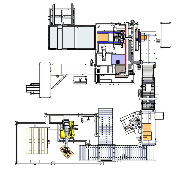
Figure 2: Guarding Arrangement
1. Electrical and Control Systems
Bector Automation RML Engineering India Pvt. Ltd. representatives have conducted a detailed and systematic Risk Assessment to identify, analyze, and mitigate potential hazards associated with the machine. The assessment has been carried out in line with internationally recognized safety practices and guidelines.
The electrical control panel is equipped with Lock Out / Tag Out (LOTO) provisions to ensure safe and complete isolation of all energy sources during maintenance and servicing activities. This includes electrical, pneumatic, and mechanical energy, thereby preventing any unintended machine start-up.
The risk assessment document systematically evaluates each section of the machine by assigning a Hazard Rating Number (HRN) to every identified hazard. This rating is derived based on the severity of injury, frequency and duration of exposure, and probability of occurrence. Hazards with higher HRN values represent more critical risks and are prioritized for implementation of appropriate risk reduction measures.
Appropriate safeguards such as fixed guarding, interlocked access doors, emergency stop systems, safety-rated control circuits, and procedural controls have been implemented to minimize risks. These measures ensure that all identified hazards are reduced to an acceptable level, providing a safe and reliable working environment for operators and maintenance personnel.
2. General requirements
As mentioned previously, with the exception of conveyors, operation and maintenance staff are separated from the moving and hazardous parts of the machine by the guard structure when the machine is energized. Access to the internal parts of the machine can only be possible when the machine has been de-energized, and the machine is deemed to be in a “Safe state”. For this reason, the safety system shall be designed and implemented to serve the sole function of de-energizing all moving or hazardous equipment when a non "Safe State" is detected.
With reference to Figure.2, and the required levels of protection (SIL 2 and PL(d)), the components required to make the safety control system will be a safety controller, safety contactors, emergency stops, door switches, photoelectric sensors and a safety air service unit. The devices within the safety control system are expected to respond, and the safety system switch, to a safe state within 0.8 seconds of any potential fault detection or safety function demand. Maximum fault detection time (i.e., determining the difference between device fault or safety function actuation) should be no more than 3 seconds. These values are determined from experience with similar machinery.
Considerations during the design phase in respect to the operating environment of the machinery were made.
-
The machinery due to its function and operating environment will not be subject to shocks or vibrations.
-
Electromagnetic compatibility is adhered to by installation of electrical components undertaken by qualified personnel.
-
The machine is designed for a non-wash down food packing environment.
-
Material selection and professional design solutions have been implemented to ensure mechanical durability.
-
It is expected the machine will be operating in ambient room temperature.
Correct maintenance of machinery componentry, both mechanical and electrical is outlined in the machinery manual that is supplied with the Stride.
Above and beyond the manufacture certifications of the devices used, correct installation and implementation of devices must be adhered too. Fault detection should cover, but is not limited too
-
Cross circuits
-
Short circuits
-
Open circuits
-
Cross terminals
2.1 HAZOP (Risk Assessment)
HAZOP, or a Hazard and Operability Study, is a systematic way to identify possible hazards in a work process. In this approach, the process is broken down into steps, and every variation in work parameters is considered for each step, to see what could go wrong. Please refer the below attachment for HAZOP Document.
2.2 Safety Contactors

Note: Click on the Image for the Component Manual
Safety contactors are used to isolate power to specific devices within the machine. The safety contactors work in conjunction with the safety controller, so that when an un-safe state is detected by the safety controller, the safety contactors work to isolate all relevant devices to allow the machine to reach a safe state. Below are the part details and a reliability block diagram (RBD) of the safety contactors to demonstrate the required architecture.

Figure.5: Safety contactor RBD
Table.4: Safety contactor part data
Description
Part No.
Quantity
Target PL
Schneider Safety Contactors
LC1D18BD
1
d
2.3 Door Switches

Click on the Image for the Component Manual
Doors are designed to restrict access into all areas where there is potential for contact with moving machinery. Access to these areas should only be allowed when the motion has stopped. All equipment is energized via the safety circuit; therefore, the safety function of the door switches is to identify access to these areas is possible by turning the safety system to a non-safe state which in turn de-energizes all machinery. Below are the part details and a reliability block diagram of the door switches to demonstrate the required architecture.

Figure.7: Door switch RBD
Table.5: Door switch part data
Description
Part No.
Quantity
PL
Safety Door Switch
STM2N-2222B024-L01-M
3
d
2.4 Photoelectric sensors
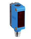
Click on the Image for the Component Manual (Sick) GTB6-P4231
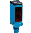
Click on the Image for the Component Manual (Sick) WTB4S-3P2261
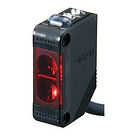
Click on the Image for the Component Manual (Omron) E3Z-LS86
The photoelectric sensor is implemented as a safety device to monitor the case blank infeed area. It verifies the presence of material before permitting machine operation. In the absence of detection, the system interprets the condition as unsafe and immediately communicates with the safety controller to inhibit or stop the machine. This arrangement ensures that the sensor functions as a critical safety element within the system.
Description
Part No.
Photoelectric sensors(Sick)
GTB6-P4231
WTB4S-3P2261
Photoelectric sensors(Omron)
E3Z-LS86
Table.6: Photoelectric sensor part data
2.5 Safety Monitored Air Service Unit

A number of the moving parts within the machinery supplied are pneumatically operated. Actuation of these pneumatic devices are electrical, however the energy associated with the mechanical movements is pneumatic. As mentioned previously, to ensure complete de-energizing of the equipment, all pneumatic devices must have their energy removed. A safety monitored dump valve is expected to achieve this if signaled to do so by the safety controller. Below are the part details and a reliability block diagram of the safety dump valve to demonstrate the required architecture.

Figure.: Air service unit RBD
Description
Part No.
Quantity
PL
Pressure Switch with Filter
MS6-SV-1/2-D-10V24-2M8-SO-AG-Z
1
d
MS6-FRM-1/2-Z
MS6-LFR-1/2-D6-C-R-M-AD12-AS-Z
MS6-EM1-1/2-S-Z
1
1
1
Table.7: Air service unit part data
3. Validation
Upon completion of the design and manufacture of this equipment, the design of the safety related parts of the control system shall be validated by a third party in accordance with AS 4024 [1], ISO 13849 [3] and/or IEC 62061 [4]. This document will form the basis for the validation by identifying the safety functions affecting the machinery supplied by Bector Automation RML India Pvt Ltd
4. Conclusion
Lupin Limited is a pharmaceutical manufacturer. Bector Automation RML Engineering India Pvt. Ltd. has been assigned to provide an automated solution to replace manual case packing on the packaging line.
The proposed solution is an adjustable Bottle Case Packer designed to handle multiple packaging formats efficiently, reducing manual intervention and improving productivity.
The scope of the project required a number of safety standards be adhered to, in particular AS4024 [1], BS EN415 [2], ISO 13849 [3] and IEC 62061 [6]. The machine is designed to be fully automatic; therefore, where permanent guarding is not practical, control systems are used to safeguard operation staff from any identified hazards (Appendix.1). The degree of safeguarding for this control system was determined to be PLd by systematic analysis using the Risk Analysis assessment with the exception of the case in feed which is to be designed in accordance with BS EN 415 [2] and have a SIL2 level of protection. The safety system implemented will serve the sole function of de-energizing all conveyor motors, servo motors, pneumatic cylinders in the event of an un-safe state. Because the machinery is fully automatic, the unsafe state is when operation staff can be exposed to any moving parts. It is required that the safety control system be validated upon completion of design, manufacture and assembly. Validation will be carried out internally by a person independent of the design of the safety systems.
5. References
[1] European Committee For Standardization, BS EN 415-7:2006 +A1 2008 Safety Of Packaging Machines
[2] ISO 13849:2006 Safety Of Machinery – Safety-related parts of control systems
[3] IEC 62061 Safety of machinery - Functional safety of safety-related electrical, electronic and programmable electronic control systems
[4] ISO 13849:1999 Safety Of Machinery – Safety-related parts of control systems