Operation of Machine

1. Shipper Magazine Assembly
1.1.3D Model
-
Product Contact Parts - SS304
-
Product Non-Contact Parts - MS, RAL 7035
Shipper Magazine
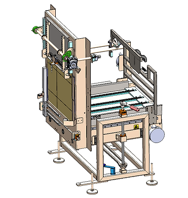
1.2 Shipper Magazine Assembly Operation
-
All shippers are stacked vertically into the magazine, and are accessed through a front opening called the picture frame.
-
The assembly consists of a sensor that detects whether there are enough shippers stacked. If the stack is low, an alarm is generated to alert the operator.
-
The magazine is motor-driven, which ensures that the shippers are always pushed forward from behind. This maintains consistent pressure, allowing each shipper to move toward the picture frame for every pluck operation.
1.3. Maintenance
Important Precautions:
-
Read this manual carefully before operating or servicing the equipment.
-
Always disconnect power and wait at least 30 seconds before connecting or disconnecting any internal harnesses. Failure to follow this may result in serious damage or destruction of the equipment.
-
Always follow proper precautions when handling static-sensitive devices.
-
Retain this manual for future reference.
-
Do not allow untrained personnel to operate, clean, inspect, maintain, service, or tamper with this equipment.
-
Do not connect or disconnect any digital or analog components while the equipment is powered ON, as this may cause damage.
Click below to access the Maintenance Schedule for the Magazine Assembly.
1.4.Risk Assessment
Risk Assessment or HAZOP, or a Hazard and Operability Study, is a systematic way to identify possible hazards in a work process. In this approach, the process is broken down into steps, and every variation in work parameters is considered for each step, to see what could go wrong.
Please refer the below attachment for HAZOP Document.
1.5. Troubleshooting
Troubleshooting is the process of identifying, diagnosing, and resolving problems or issues that arise in various systems, equipment, or processes. it involves a systematic approach to problem-solving, using a combination of analytical, technical, and problem-solving skills.
The first step in troubleshooting is to identify the problem. This can involve gathering information about the issue, including when it started, what systems or equipment are affected, and any error messages or symptoms that are observed. Once the problem is identified, the next step is to diagnose the root cause. This involves analyzing the information collected and using technical knowledge to determine what is causing the issue. After the root cause is identified, the next step is to develop a plan for resolving the issue.
Refer to the below about the Troubleshooting.
1.6 Spare List
Shipper Magazine & Picture Frame Assembly
Note: Click on the Description for details about Spare parts
Description
Consumables
Essential
Recomended
Sr No.
1.
2.
1
1
Gear Motor
Adjustment Gearbox
1
1
2. Shipper Plucker Assembly
2.1.3D Model
-
Product Contact Parts - SS304
-
Product Non-Contact Parts - MS, RAL 7035
Shipper Plucker Assembly
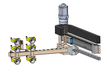
2.2 Shipper Plucker Assembly Operation
-
The Shipper Plucker Assembly is a vacuum-based Plucker assisted by a servo mechanism.
-
The Plucker grips the front surface of the shipper at the picture frame and then plucks it out using the servo.
-
After plucking, the shipper is formed and positioned over the flap folding assembly, where the flap folding operation is performed on the inserted shipper.
2.3. Maintenance
Important Precautions:
-
Read this manual carefully before operating or servicing the equipment.
-
Always disconnect power and wait at least 30 seconds before connecting or disconnecting any internal harnesses. Failure to follow this may result in serious damage or destruction of the equipment.
-
Always follow proper precautions when handling static-sensitive devices.
-
Retain this manual for future reference.
-
Do not allow untrained personnel to operate, clean, inspect, maintain, service, or tamper with this equipment.
-
Do not connect or disconnect any digital or analog components while the equipment is powered ON, as this may cause damage.
Click below to access the Maintenance Schedule for the Shipper Plucker Assembly.
2.4. Risk Assessment
Risk Assessment or HAZOP, or a Hazard and Operability Study, is a systematic way to identify possible hazards in a work process. In this approach, the process is broken down into steps, and every variation in work parameters is considered for each step, to see what could go wrong.
Please refer the below attachment for HAZOP Document.
2.5. Troubleshooting
Troubleshooting is the process of identifying, diagnosing, and resolving problems or issues that arise in various systems, equipment, or processes. it involves a systematic approach to problem-solving, using a combination of analytical, technical, and problem-solving skills.
The first step in troubleshooting is to identify the problem. This can involve gathering information about the issue, including when it started, what systems or equipment are affected, and any error messages or symptoms that are observed. Once the problem is identified, the next step is to diagnose the root cause. This involves analyzing the information collected and using technical knowledge to determine what is causing the issue. After the root cause is identified, the next step is to develop a plan for resolving the issue.
Refer to the below about the Troubleshooting.
2.6 Spare List
Note: Click on the Description for details about Spare parts
3.
5.
Description
Consumables
Essential
Recomended
Sr No.
1.
2.
4.
6.
7.
8.
5
5
1
1
1
Folder Product Tray
Plastic Product Tray
AT10 Drive Belt
Metric Pulleys AT10, 32mm belt
Metric Pulleys AT10, 32mm belt
LDK TP-F 205 Hsg 4-Bolt Flange
NTN UC205-25
1
1
SIL 110 9.19ID x 14.3OD N70 O-Ring
4
Parth Magnetic Door Catch
FALSE TOOTH
AT10 Belt
Madler Keyless Coupling
Drive Pulley
Pulley Side Disc
Drive Shaft
Driven Shaft
PACKING BUSH
DOWELL
neodumium magnet N52
SILICON PAD
9.
10.
11.
12.
13.
14.
15.
16.
17.
18.
19.
20.
5
5
5
5
1
1
2
1
1
1
10
1
3. Flap Floding Assembly
3.1.3D Model
-
Product Contact Parts - SS304,
-
Product Non-Contact Parts - MS, RAL 7035
Flap Folding Assembly

3.2 Flap Folding Assembly Operation
-
The Flap Folding Assembly is used for folding and tucking the the bottom flaps of the shipper do the subsequent sealing with tape.
-
It consists of four cylinders that close the two minor flaps and two major flap of the shipper, which operate after the shipper has been -plucked and formed properly.
3.3. Maintenance
Important Precautions:
-
Read this manual carefully before operating or servicing the equipment.
-
Always disconnect power and wait at least 30 seconds before connecting or disconnecting any internal harnesses. Failure to follow this may result in serious damage or destruction of the equipment.
-
Always follow proper precautions when handling static-sensitive devices.
-
Retain this manual for future reference.
-
Do not allow untrained personnel to operate, clean, inspect, maintain, service, or tamper with this equipment.
-
Do not connect or disconnect any digital or analog components while the equipment is powered ON, as this may cause damage.
Click below to access the Maintenance Schedule for the Flap Folding Assembly.
3.4. Risk Assessment
Risk Assessment or HAZOP, or a Hazard and Operability Study, is a systematic way to identify possible hazards in a work process. In this approach, the process is broken down into steps, and every variation in work parameters is considered for each step, to see what could go wrong.
Please refer the below attachment for HAZOP Document.
3.5. Troubleshooting
Troubleshooting is the process of identifying, diagnosing, and resolving problems or issues that arise in various systems, equipment, or processes. it involves a systematic approach to problem-solving, using a combination of analytical, technical, and problem-solving skills.
The first step in troubleshooting is to identify the problem. This can involve gathering information about the issue, including when it started, what systems or equipment are affected, and any error messages or symptoms that are observed. Once the problem is identified, the next step is to diagnose the root cause. This involves analyzing the information collected and using technical knowledge to determine what is causing the issue. After the root cause is identified, the next step is to develop a plan for resolving the issue.
Refer to the below about the Troubleshooting.
3.6 Spare List
Note: Click on the Description for details about Spare parts
3.
5.
Description
Consumables
Essential
Recomended
Sr No.
1.
2.
4.
6.
7.
8.
5
5
1
1
1
Folder Product Tray
Plastic Product Tray
AT10 Drive Belt
Metric Pulleys AT10, 32mm belt
Metric Pulleys AT10, 32mm belt
LDK TP-F 205 Hsg 4-Bolt Flange
NTN UC205-25
1
1
SIL 110 9.19ID x 14.3OD N70 O-Ring
4
Parth Magnetic Door Catch
FALSE TOOTH
AT10 Belt
Madler Keyless Coupling
Drive Pulley
Pulley Side Disc
Drive Shaft
Driven Shaft
PACKING BUSH
DOWELL
neodumium magnet N52
SILICON PAD
9.
10.
11.
12.
13.
14.
15.
16.
17.
18.
19.
20.
5
5
5
5
1
1
2
1
1
1
10
1
4. Bottom Taping Assembly
4.1.3D Model
-
Product Contact Parts - SS304,
-
Product Non-Contact Parts - MS, RAL 7035
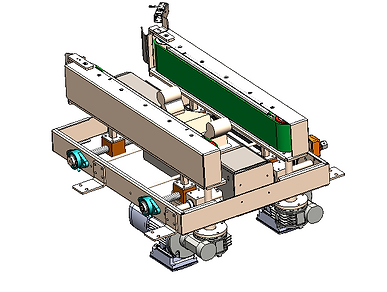
Bottom Taping Assembly
4.2 Bottom Taping Assembly Operation
-
The Bottom Taping Machine is used for sealing the bottom of the shipper after the flaps have been folded in the flap folding assembly.
-
The shipper is fed into the taping machine by a pusher from the flap folding assembly. It is then guided and moved by two side conveyors, which are motor-driven to ensure smooth and consistent transport through the taping head.
-
The taping head mechanism applies the tape to the bottom of the shipper, sealing it completely.
-
The PE sensor is present at the tape roll, where the presence of the tape roll is detected. If empty, it gives feedback to generate the alarm.
-
After sealing, the shipper is transferred to the Main Drive via,ready for further handling or packing.
4.3. Maintenance
Important Precautions:
-
Read this manual carefully before operating or servicing the equipment.
-
Always disconnect power and wait at least 30 seconds before connecting or disconnecting any internal harnesses. Failure to follow this may result in serious damage or destruction of the equipment.
-
Always follow proper precautions when handling static-sensitive devices.
-
Retain this manual for future reference.
-
Do not allow untrained personnel to operate, clean, inspect, maintain, service, or tamper with this equipment.
-
Do not connect or disconnect any digital or analog components while the equipment is powered ON, as this may cause damage.
Click below to access the Maintenance Schedule for the Bottom Taping Assembly.
4.4. Risk Assessment
Risk Assessment or HAZOP, or a Hazard and Operability Study, is a systematic way to identify possible hazards in a work process. In this approach, the process is broken down into steps, and every variation in work parameters is considered for each step, to see what could go wrong.
Please refer the below attachment for HAZOP Document.
4.5. Troubleshooting
Troubleshooting is the process of identifying, diagnosing, and resolving problems or issues that arise in various systems, equipment, or processes. it involves a systematic approach to problem-solving, using a combination of analytical, technical, and problem-solving skills.
The first step in troubleshooting is to identify the problem. This can involve gathering information about the issue, including when it started, what systems or equipment are affected, and any error messages or symptoms that are observed. Once the problem is identified, the next step is to diagnose the root cause. This involves analyzing the information collected and using technical knowledge to determine what is causing the issue. After the root cause is identified, the next step is to develop a plan for resolving the issue.
Refer to the below about the Troubleshooting.
4.6 Spare List
Note: Click on the Description for details about Spare parts
3.
5.
Description
Consumables
Essential
Recomended
Sr No.
1.
2.
4.
6.
7.
8.
5
5
1
1
1
Folder Product Tray
Plastic Product Tray
AT10 Drive Belt
Metric Pulleys AT10, 32mm belt
Metric Pulleys AT10, 32mm belt
LDK TP-F 205 Hsg 4-Bolt Flange
NTN UC205-25
1
1
SIL 110 9.19ID x 14.3OD N70 O-Ring
4
Parth Magnetic Door Catch
FALSE TOOTH
AT10 Belt
Madler Keyless Coupling
Drive Pulley
Pulley Side Disc
Drive Shaft
Driven Shaft
PACKING BUSH
DOWELL
neodumium magnet N52
SILICON PAD
9.
10.
11.
12.
13.
14.
15.
16.
17.
18.
19.
20.
5
5
5
5
1
1
2
1
1
1
10
1
5. Hopper and Main drive Assembly
5.1.3D Model
-
Product Contact Parts - SS304,
-
Product Non-Contact Parts - MS, RAL 7035
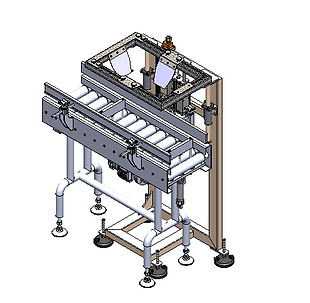
Hopper Assembly
5.2 Hopper and Main Drive Assembly Operation
-
The Hopper and Main drive Assembly is used to receive shippers from the Bottom Taping Machine and position them correctly for the next operation.
-
It consists of a hopper that temporarily holds the shipper, and a cylinder that descends the hopper into the top open cylinder for precise placement.
-
Two additional cylinders act as stoppers — one at the hopper and one before it — functioning as to control the shipper’s position accurately.
-
Then ensuring the shipper is ready for the robot operation.
-
After the robot places the matrix, the shipper is transferred smoothly to the Top Taping Assembly for the final sealing operation.
5.3. Maintenance
Important Precautions:
-
Read this manual carefully before operating or servicing the equipment.
-
Always disconnect power and wait at least 30 seconds before connecting or disconnecting any internal harnesses. Failure to follow this may result in serious damage or destruction of the equipment.
-
Always follow proper precautions when handling static-sensitive devices.
-
Retain this manual for future reference.
-
Do not allow untrained personnel to operate, clean, inspect, maintain, service, or tamper with this equipment.
-
Do not connect or disconnect any digital or analog components while the equipment is powered ON, as this may cause damage.
Click below to access the Maintenance Schedule for the Hopper & Main Drive Assembly.
5.4. Risk Assessment
Risk Assessment or HAZOP, or a Hazard and Operability Study, is a systematic way to identify possible hazards in a work process. In this approach, the process is broken down into steps, and every variation in work parameters is considered for each step, to see what could go wrong.
Please refer the below attachment for HAZOP Document.
5.5. Troubleshooting
Troubleshooting is the process of identifying, diagnosing, and resolving problems or issues that arise in various systems, equipment, or processes. it involves a systematic approach to problem-solving, using a combination of analytical, technical, and problem-solving skills.
The first step in troubleshooting is to identify the problem. This can involve gathering information about the issue, including when it started, what systems or equipment are affected, and any error messages or symptoms that are observed. Once the problem is identified, the next step is to diagnose the root cause. This involves analyzing the information collected and using technical knowledge to determine what is causing the issue. After the root cause is identified, the next step is to develop a plan for resolving the issue.
Refer to the below about the Troubleshooting.
5.6 Spare List
Note: Click on the Description for details about Spare parts
3.
5.
Description
Consumables
Essential
Recomended
Sr No.
1.
2.
4.
6.
7.
8.
5
5
1
1
1
Folder Product Tray
Plastic Product Tray
AT10 Drive Belt
Metric Pulleys AT10, 32mm belt
Metric Pulleys AT10, 32mm belt
LDK TP-F 205 Hsg 4-Bolt Flange
NTN UC205-25
1
1
SIL 110 9.19ID x 14.3OD N70 O-Ring
4
Parth Magnetic Door Catch
FALSE TOOTH
AT10 Belt
Madler Keyless Coupling
Drive Pulley
Pulley Side Disc
Drive Shaft
Driven Shaft
PACKING BUSH
DOWELL
neodumium magnet N52
SILICON PAD
9.
10.
11.
12.
13.
14.
15.
16.
17.
18.
19.
20.
5
5
5
5
1
1
2
1
1
1
10
1
6.Infeed Conveyor (For Bundle Bottles )
6.1. 3D Model
-
Product Contact Parts - SS304
-
Product Non-Contact Parts - MS, RAL 7035
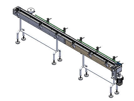
Infeed Conveyor
6.2. Infeed Conveyor operation
-
The infeed conveyor assembly receives the product from the Bottle Infeed Conveyor / Source Machine and transfers it towards the Collation Platform Assembly for further processing.
-
The conveyor consists of a motor-driven belt system with sensors to detect product presence and ensure proper spacing and flow.
-
Based on the product detection, the conveyor moves the products forward at a controlled speed.
-
The assembly operates continuously and ensures smooth and consistent feeding of products to the collation unit for matrix formation.
6.3. Maintenance
Important Precautions:
-
Read this manual carefully before operating or servicing the equipment.
-
Always disconnect power and wait at least 30 seconds before connecting or disconnecting any internal harnesses. Failure to follow this may result in serious damage or destruction of the equipment.
-
Always follow proper precautions when handling static-sensitive devices.
-
Retain this manual for future reference.
-
Do not allow untrained personnel to operate, clean, inspect, maintain, service, or tamper with this equipment.
-
Do not connect or disconnect any digital or analog components while the equipment is powered ON, as this may cause damage.
Click below to access the Maintenance Schedule for the Infeed Conveyor Assembly.
6.4. Risk Assessment
Risk Assessment or HAZOP, or a Hazard and Operability Study, is a systematic way to identify possible hazards in a work process. In this approach, the process is broken down into steps, and every variation in work parameters is considered for each step, to see what could go wrong.
Please refer the below attachment for HAZOP Document.
6.5. Troubleshooting
Troubleshooting is the process of identifying, diagnosing, and resolving problems or issues that arise in various systems, equipment, or processes. it involves a systematic approach to problem-solving, using a combination of analytical, technical, and problem-solving skills.
The first step in troubleshooting is to identify the problem. This can involve gathering information about the issue, including when it started, what systems or equipment are affected, and any error messages or symptoms that are observed. Once the problem is identified, the next step is to diagnose the root cause. This involves analyzing the information collected and using technical knowledge to determine what is causing the issue. After the root cause is identified, the next step is to develop a plan for resolving the issue.
Refer to the below about the Troubleshooting.
6.6 Spare List
Note: Click on the Description for details about Spare parts
3.
5.
Description
Consumables
Essential
Recomended
Sr No.
1.
2.
4.
6.
7.
8.
5
5
1
1
1
Folder Product Tray
Plastic Product Tray
AT10 Drive Belt
Metric Pulleys AT10, 32mm belt
Metric Pulleys AT10, 32mm belt
LDK TP-F 205 Hsg 4-Bolt Flange
NTN UC205-25
1
1
SIL 110 9.19ID x 14.3OD N70 O-Ring
4
Parth Magnetic Door Catch
FALSE TOOTH
AT10 Belt
Madler Keyless Coupling
Drive Pulley
Pulley Side Disc
Drive Shaft
Driven Shaft
PACKING BUSH
DOWELL
neodumium magnet N52
SILICON PAD
9.
10.
11.
12.
13.
14.
15.
16.
17.
18.
19.
20.
5
5
5
5
1
1
2
1
1
1
10
1
7.Infeed Conveyor (For loose Bottles)
7.1. 3D Model
-
Product Contact Parts - SS304
-
Product Non-Contact Parts - MS, RAL 7035
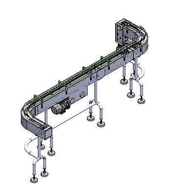
Infeed Conveyor
7.2. Infeed Conveyor operation
-
The infeed conveyor assembly receives the Loose bottles from the Loose Bottle Source / Previous Assembly and transfers them towards the Collation Platform Assembly for further processing.
-
The conveyor consists of a motor-driven belt system with sensors to detect Loose presence and ensure proper flow.
-
Based on the bundle detection, the conveyor moves the Loose Bottle forward at a controlled speed.
-
The assembly operates continuously and ensures smooth and consistent feeding of Loose bottles to the collation unit for matrix formation.
7.3. Maintenance
Important Precautions:
-
Read this manual carefully before operating or servicing the equipment.
-
Always disconnect power and wait at least 30 seconds before connecting or disconnecting any internal harnesses. Failure to follow this may result in serious damage or destruction of the equipment.
-
Always follow proper precautions when handling static-sensitive devices.
-
Retain this manual for future reference.
-
Do not allow untrained personnel to operate, clean, inspect, maintain, service, or tamper with this equipment.
-
Do not connect or disconnect any digital or analog components while the equipment is powered ON, as this may cause damage.
Click below to access the Maintenance Schedule for the Infeed Conveyor Assembly.
7.4. Risk Assessment
Risk Assessment or HAZOP, or a Hazard and Operability Study, is a systematic way to identify possible hazards in a work process. In this approach, the process is broken down into steps, and every variation in work parameters is considered for each step, to see what could go wrong.
Please refer the below attachment for HAZOP Document.
7.5. Troubleshooting
Troubleshooting is the process of identifying, diagnosing, and resolving problems or issues that arise in various systems, equipment, or processes. it involves a systematic approach to problem-solving, using a combination of analytical, technical, and problem-solving skills.
The first step in troubleshooting is to identify the problem. This can involve gathering information about the issue, including when it started, what systems or equipment are affected, and any error messages or symptoms that are observed. Once the problem is identified, the next step is to diagnose the root cause. This involves analyzing the information collected and using technical knowledge to determine what is causing the issue. After the root cause is identified, the next step is to develop a plan for resolving the issue.
Refer to the below about the Troubleshooting.
7.6 Spare List
Note: Click on the Description for details about Spare parts
3.
5.
Description
Consumables
Essential
Recomended
Sr No.
1.
2.
4.
6.
7.
8.
5
5
1
1
1
Folder Product Tray
Plastic Product Tray
AT10 Drive Belt
Metric Pulleys AT10, 32mm belt
Metric Pulleys AT10, 32mm belt
LDK TP-F 205 Hsg 4-Bolt Flange
NTN UC205-25
1
1
SIL 110 9.19ID x 14.3OD N70 O-Ring
4
Parth Magnetic Door Catch
FALSE TOOTH
AT10 Belt
Madler Keyless Coupling
Drive Pulley
Pulley Side Disc
Drive Shaft
Driven Shaft
PACKING BUSH
DOWELL
neodumium magnet N52
SILICON PAD
9.
10.
11.
12.
13.
14.
15.
16.
17.
18.
19.
20.
5
5
5
5
1
1
2
1
1
1
10
1
8. Collation Platform Assembly
8.1.3D Model
-
Product Contact Parts - SS304,
-
Product Non-Contact Parts - MS, RAL 7035
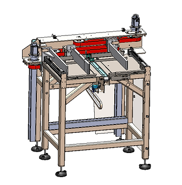
collation platform Assembly
8.2 Collation Platform Assembly Operation
-
The collation platform assembly is used to form the product matrix for the robot to pick and place into the shipper using a servo-based positioning system for accurate control.
-
The working involves receiving products from the Infeed Conveyor Assembly and arranging them into two matrix formations based on the selected configuration, including loose bundle (36 bottles) and other bundle configurations as per product data.
-
The system ensures that at least one matrix is completely formed and properly aligned before sending a signal to the robot for pick-and-place operation, while the second matrix continues forming to maintain continuous flow.
8.3. Maintenance
Important Precautions:
-
Read this manual carefully before operating or servicing the equipment.
-
Always disconnect power and wait at least 30 seconds before connecting or disconnecting any internal harnesses. Failure to follow this may result in serious damage or destruction of the equipment.
-
Always follow proper precautions when handling static-sensitive devices.
-
Retain this manual for future reference.
-
Do not allow untrained personnel to operate, clean, inspect, maintain, service, or tamper with this equipment.
-
Do not connect or disconnect any digital or analog components while the equipment is powered ON, as this may cause damage.
Click below to access the Maintenance Schedule for the Collation Conveyor Assembly.
8.4. Risk Assessment
Risk Assessment or HAZOP, or a Hazard and Operability Study, is a systematic way to identify possible hazards in a work process. In this approach, the process is broken down into steps, and every variation in work parameters is considered for each step, to see what could go wrong.
Please refer the below attachment for HAZOP Document.
8.5. Troubleshooting
Troubleshooting is the process of identifying, diagnosing, and resolving problems or issues that arise in various systems, equipment, or processes. it involves a systematic approach to problem-solving, using a combination of analytical, technical, and problem-solving skills.
The first step in troubleshooting is to identify the problem. This can involve gathering information about the issue, including when it started, what systems or equipment are affected, and any error messages or symptoms that are observed. Once the problem is identified, the next step is to diagnose the root cause. This involves analyzing the information collected and using technical knowledge to determine what is causing the issue. After the root cause is identified, the next step is to develop a plan for resolving the issue.
Refer to the below about the Troubleshooting.
8.6 Spare List
Note: Click on the Description for details about Spare parts
3.
5.
Description
Consumables
Essential
Recomended
Sr No.
1.
2.
4.
6.
7.
8.
5
5
1
1
1
Folder Product Tray
Plastic Product Tray
AT10 Drive Belt
Metric Pulleys AT10, 32mm belt
Metric Pulleys AT10, 32mm belt
LDK TP-F 205 Hsg 4-Bolt Flange
NTN UC205-25
1
1
SIL 110 9.19ID x 14.3OD N70 O-Ring
4
Parth Magnetic Door Catch
FALSE TOOTH
AT10 Belt
Madler Keyless Coupling
Drive Pulley
Pulley Side Disc
Drive Shaft
Driven Shaft
PACKING BUSH
DOWELL
neodumium magnet N52
SILICON PAD
9.
10.
11.
12.
13.
14.
15.
16.
17.
18.
19.
20.
5
5
5
5
1
1
2
1
1
1
10
1
9.Scara Robot for Matrix Pick & Place
9.1. 3D Model
9.2. Robot operation
-
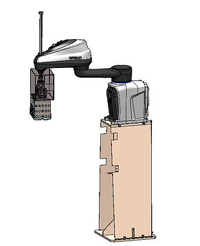
The matrix transfer robot (i4-750H) receives the product matrix from the Collation Platform Assembly once the matrix formation is completed and a ready signal is generated.
-
Based on this signal, the robot performs pick operation by lifting the complete matrix using its gripper mechanism with precise positioning and synchronization.
-
The robot then transfers and places the picked matrix into the hopper of the Main Drive Assembly, ensuring correct placement and alignment for further processing.
-
The robot operates in continuous cycle, coordinating with the collation unit to maintain smooth flow of products and ensuring efficient transfer without interruption.
9.3. Maintenance
Important Precautions:
-
Read this manual carefully before operating or servicing the equipment.
-
Always disconnect power and wait at least 30 seconds before connecting or disconnecting any internal harnesses. Failure to follow this may result in serious damage or destruction of the equipment.
-
Always follow proper precautions when handling static-sensitive devices.
-
Retain this manual for future reference.
-
Do not allow untrained personnel to operate, clean, inspect, maintain, service, or tamper with this equipment.
-
Do not connect or disconnect any digital or analog components while the equipment is powered ON, as this may cause damage.
Click below to access the Maintenance Schedule for the Scara Robot for Matrix Pick & Place
9.4. Risk Assessment
Risk Assessment or HAZOP, or a Hazard and Operability Study, is a systematic way to identify possible hazards in a work process. In this approach, the process is broken down into steps, and every variation in work parameters is considered for each step, to see what could go wrong.
Please refer the below attachment for HAZOP Document.
9.5. Troubleshooting
Troubleshooting is the process of identifying, diagnosing, and resolving problems or issues that arise in various systems, equipment, or processes. it involves a systematic approach to problem-solving, using a combination of analytical, technical, and problem-solving skills.
The first step in troubleshooting is to identify the problem. This can involve gathering information about the issue, including when it started, what systems or equipment are affected, and any error messages or symptoms that are observed. Once the problem is identified, the next step is to diagnose the root cause. This involves analyzing the information collected and using technical knowledge to determine what is causing the issue. After the root cause is identified, the next step is to develop a plan for resolving the issue.
Refer to the below about the Troubleshooting.
9.6 Spare List
Note: Click on the Description for details about Spare parts
3.
5.
Description
Consumables
Essential
Recomended
Sr No.
1.
2.
4.
6.
7.
8.
5
5
1
1
1
Folder Product Tray
Plastic Product Tray
AT10 Drive Belt
Metric Pulleys AT10, 32mm belt
Metric Pulleys AT10, 32mm belt
LDK TP-F 205 Hsg 4-Bolt Flange
NTN UC205-25
1
1
SIL 110 9.19ID x 14.3OD N70 O-Ring
4
Parth Magnetic Door Catch
FALSE TOOTH
AT10 Belt
Madler Keyless Coupling
Drive Pulley
Pulley Side Disc
Drive Shaft
Driven Shaft
PACKING BUSH
DOWELL
neodumium magnet N52
SILICON PAD
9.
10.
11.
12.
13.
14.
15.
16.
17.
18.
19.
20.
5
5
5
5
1
1
2
1
1
1
10
1
10.Layer Board Magazine
10.1. 3D Model
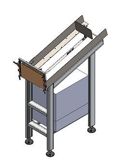
Layer Board Magazine
10.2. Layer Board Magazine operation
-
Layer Board Magazine Assembly and allows it to move towards the robot pick position using gravity.
-
The conveyor consists of free rollers mounted on a sloped structure, and the PLC control panel is mounted under the conveyor.
-
The layer board moves automatically due to gravity and reaches the defined pick location for the robot.
-
The assembly ensures simple, smooth, and continuous supply of layer boards for proper placement inside the shipper.
10.3. Maintenance
Important Precautions:
-
Read this manual carefully before operating or servicing the equipment.
-
Always disconnect power and wait at least 30 seconds before connecting or disconnecting any internal harnesses. Failure to follow this may result in serious damage or destruction of the equipment.
-
Always follow proper precautions when handling static-sensitive devices.
-
Retain this manual for future reference.
-
Do not allow untrained personnel to operate, clean, inspect, maintain, service, or tamper with this equipment.
-
Do not connect or disconnect any digital or analog components while the equipment is powered ON, as this may cause damage.
Click below to access the Maintenance Schedule for the Layer Borad Magazine Assembly.
10.4. Risk Assessment
Risk Assessment or HAZOP, or a Hazard and Operability Study, is a systematic way to identify possible hazards in a work process. In this approach, the process is broken down into steps, and every variation in work parameters is considered for each step, to see what could go wrong.
Please refer the below attachment for HAZOP Document.
10.5. Troubleshooting
Troubleshooting is the process of identifying, diagnosing, and resolving problems or issues that arise in various systems, equipment, or processes. it involves a systematic approach to problem-solving, using a combination of analytical, technical, and problem-solving skills.
The first step in troubleshooting is to identify the problem. This can involve gathering information about the issue, including when it started, what systems or equipment are affected, and any error messages or symptoms that are observed. Once the problem is identified, the next step is to diagnose the root cause. This involves analyzing the information collected and using technical knowledge to determine what is causing the issue. After the root cause is identified, the next step is to develop a plan for resolving the issue.
Refer to the below about the Troubleshooting.
10.6 Spare List
Note: Click on the Description for details about Spare parts
3.
5.
Description
Consumables
Essential
Recomended
Sr No.
1.
2.
4.
6.
7.
8.
5
5
1
1
1
Folder Product Tray
Plastic Product Tray
AT10 Drive Belt
Metric Pulleys AT10, 32mm belt
Metric Pulleys AT10, 32mm belt
LDK TP-F 205 Hsg 4-Bolt Flange
NTN UC205-25
1
1
SIL 110 9.19ID x 14.3OD N70 O-Ring
4
Parth Magnetic Door Catch
FALSE TOOTH
AT10 Belt
Madler Keyless Coupling
Drive Pulley
Pulley Side Disc
Drive Shaft
Driven Shaft
PACKING BUSH
DOWELL
neodumium magnet N52
SILICON PAD
9.
10.
11.
12.
13.
14.
15.
16.
17.
18.
19.
20.
5
5
5
5
1
1
2
1
1
1
10
1
11.Scara Robot for Layer Board Pick & Place
11.1. 3D Model
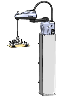
11.2.Scara Robot For Layer Board Pick & Place operation
-
The robot (i4-550L) picks the shipper from the magazine/picture frame and transfers it to Vacuum Station-1 for further operation.
-
The robot holds the shipper using vacuum cups, opens the shipper, and places it at Vacuum Station-2 for positioning.For 118 ml shrink-wrap bundles, the robot checks layer board low-level detect and picks the layer board from the magazine when required.
-
The robot places the layer board at the bottom or middle of the shipper based on product matrix placement to ensure proper stacking and support.
11.3. Maintenance
Important Precautions:
-
Read this manual carefully before operating or servicing the equipment.
-
Always disconnect power and wait at least 30 seconds before connecting or disconnecting any internal harnesses. Failure to follow this may result in serious damage or destruction of the equipment.
-
Always follow proper precautions when handling static-sensitive devices.
-
Retain this manual for future reference.
-
Do not allow untrained personnel to operate, clean, inspect, maintain, service, or tamper with this equipment.
-
Do not connect or disconnect any digital or analog components while the equipment is powered ON, as this may cause damage.
Click below to access the Maintenance Schedule for the Scara Robot for Layer Board Pick& Place Magazine Conveyor Assembly.
11.4. Risk Assessment
Risk Assessment or HAZOP, or a Hazard and Operability Study, is a systematic way to identify possible hazards in a work process. In this approach, the process is broken down into steps, and every variation in work parameters is considered for each step, to see what could go wrong.
Please refer the below attachment for HAZOP Document.
11.5. Troubleshooting
Troubleshooting is the process of identifying, diagnosing, and resolving problems or issues that arise in various systems, equipment, or processes. it involves a systematic approach to problem-solving, using a combination of analytical, technical, and problem-solving skills.
The first step in troubleshooting is to identify the problem. This can involve gathering information about the issue, including when it started, what systems or equipment are affected, and any error messages or symptoms that are observed. Once the problem is identified, the next step is to diagnose the root cause. This involves analyzing the information collected and using technical knowledge to determine what is causing the issue. After the root cause is identified, the next step is to develop a plan for resolving the issue.
Refer to the below about the Troubleshooting.
11.6 Spare List
Note: Click on the Description for details about Spare parts
3.
5.
Description
Consumables
Essential
Recomended
Sr No.
1.
2.
4.
6.
7.
8.
5
5
1
1
1
Folder Product Tray
Plastic Product Tray
AT10 Drive Belt
Metric Pulleys AT10, 32mm belt
Metric Pulleys AT10, 32mm belt
LDK TP-F 205 Hsg 4-Bolt Flange
NTN UC205-25
1
1
SIL 110 9.19ID x 14.3OD N70 O-Ring
4
Parth Magnetic Door Catch
FALSE TOOTH
AT10 Belt
Madler Keyless Coupling
Drive Pulley
Pulley Side Disc
Drive Shaft
Driven Shaft
PACKING BUSH
DOWELL
neodumium magnet N52
SILICON PAD
9.
10.
11.
12.
13.
14.
15.
16.
17.
18.
19.
20.
5
5
5
5
1
1
2
1
1
1
10
1
12.Rotary Roller Conveyor
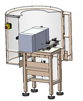
12.1. 3D Model
Rotary Roller Conveyor
12.2. Rotary Roller Conveyor operation
-
The rotary roller conveyor receives the shipper after taping, where taping confirmation is received before further movement.
-
Once the taping is confirmed, a signal is generated and the shipper is pulled onto the rotary conveyor section.
-
The conveyor then rotates the shipper by 90 degrees to change its orientation as required for downstream process.
-
After rotation, the shipper is transferred to the next roller conveyor for further operation.
12.3. Maintenance
Important Precautions:
-
Read this manual carefully before operating or servicing the equipment.
-
Always disconnect power and wait at least 30 seconds before connecting or disconnecting any internal harnesses. Failure to follow this may result in serious damage or destruction of the equipment.
-
Always follow proper precautions when handling static-sensitive devices.
-
Retain this manual for future reference.
-
Do not allow untrained personnel to operate, clean, inspect, maintain, service, or tamper with this equipment.
-
Do not connect or disconnect any digital or analog components while the equipment is powered ON, as this may cause damage.
Click below to access the Maintenance Schedule for the Magazine Conveyor Assembly.
12.4. Risk Assessment
Risk Assessment or HAZOP, or a Hazard and Operability Study, is a systematic way to identify possible hazards in a work process. In this approach, the process is broken down into steps, and every variation in work parameters is considered for each step, to see what could go wrong.
Please refer the below attachment for HAZOP Document.
12.5. Troubleshooting
Troubleshooting is the process of identifying, diagnosing, and resolving problems or issues that arise in various systems, equipment, or processes. it involves a systematic approach to problem-solving, using a combination of analytical, technical, and problem-solving skills.
The first step in troubleshooting is to identify the problem. This can involve gathering information about the issue, including when it started, what systems or equipment are affected, and any error messages or symptoms that are observed. Once the problem is identified, the next step is to diagnose the root cause. This involves analyzing the information collected and using technical knowledge to determine what is causing the issue. After the root cause is identified, the next step is to develop a plan for resolving the issue.
Refer to the below about the Troubleshooting.
12.6 Spare List
Note: Click on the Description for details about Spare parts
3.
5.
Description
Consumables
Essential
Recomended
Sr No.
1.
2.
4.
6.
7.
8.
5
5
1
1
1
Folder Product Tray
Plastic Product Tray
AT10 Drive Belt
Metric Pulleys AT10, 32mm belt
Metric Pulleys AT10, 32mm belt
LDK TP-F 205 Hsg 4-Bolt Flange
NTN UC205-25
1
1
SIL 110 9.19ID x 14.3OD N70 O-Ring
4
Parth Magnetic Door Catch
FALSE TOOTH
AT10 Belt
Madler Keyless Coupling
Drive Pulley
Pulley Side Disc
Drive Shaft
Driven Shaft
PACKING BUSH
DOWELL
neodumium magnet N52
SILICON PAD
9.
10.
11.
12.
13.
14.
15.
16.
17.
18.
19.
20.
5
5
5
5
1
1
2
1
1
1
10
1
13. Top Taping Assembly
13.1.3D Model

Top taping Assembly
-
Product Contact Parts - SS304,
-
Product Non-Contact Parts - MS, RAL 7035
13.2 Top Taping Assembly Operation
-
The assembly consists of cylinder mechanisms that fold and close the top major and minor flaps of the shipper before the tape is applied.
-
A photoelectric sensor at the start detects after the presence of the shipper to ensure the operation only begins when a shipper is correctly in position.
-
Another sensor is mounted near the tape roll to detect if the tape is running low or has run out, providing an alert to the operator and preventing incomplete sealing.
-
Once the flaps are folded and the tape is applied, the shipper is completely sealed and ready for further handling or packing.
13.3. Maintenance
Important Precautions:
-
Read this manual carefully before operating or servicing the equipment.
-
Always disconnect power and wait at least 30 seconds before connecting or disconnecting any internal harnesses. Failure to follow this may result in serious damage or destruction of the equipment.
-
Always follow proper precautions when handling static-sensitive devices.
-
Retain this manual for future reference.
-
Do not allow untrained personnel to operate, clean, inspect, maintain, service, or tamper with this equipment.
-
Do not connect or disconnect any digital or analog components while the equipment is powered ON, as this may cause damage.
Click below to access the Maintenance Schedule for the Top Taping Assembly.
13.4. Risk Assessment
Risk Assessment or HAZOP, or a Hazard and Operability Study, is a systematic way to identify possible hazards in a work process. In this approach, the process is broken down into steps, and every variation in work parameters is considered for each step, to see what could go wrong.
Please refer the below attachment for HAZOP Document.
13.5. Troubleshooting
Troubleshooting is the process of identifying, diagnosing, and resolving problems or issues that arise in various systems, equipment, or processes. it involves a systematic approach to problem-solving, using a combination of analytical, technical, and problem-solving skills.
The first step in troubleshooting is to identify the problem. This can involve gathering information about the issue, including when it started, what systems or equipment are affected, and any error messages or symptoms that are observed. Once the problem is identified, the next step is to diagnose the root cause. This involves analyzing the information collected and using technical knowledge to determine what is causing the issue. After the root cause is identified, the next step is to develop a plan for resolving the issue.
Refer to the below about the Troubleshooting.
13.6 Spare List
Note: Click on the Description for details about Spare parts
3.
5.
Description
Consumables
Essential
Recomended
Sr No.
1.
2.
4.
6.
7.
8.
5
5
1
1
1
Folder Product Tray
Plastic Product Tray
AT10 Drive Belt
Metric Pulleys AT10, 32mm belt
Metric Pulleys AT10, 32mm belt
LDK TP-F 205 Hsg 4-Bolt Flange
NTN UC205-25
1
1
SIL 110 9.19ID x 14.3OD N70 O-Ring
4
Parth Magnetic Door Catch
FALSE TOOTH
AT10 Belt
Madler Keyless Coupling
Drive Pulley
Pulley Side Disc
Drive Shaft
Driven Shaft
PACKING BUSH
DOWELL
neodumium magnet N52
SILICON PAD
9.
10.
11.
12.
13.
14.
15.
16.
17.
18.
19.
20.
5
5
5
5
1
1
2
1
1
1
10
1
14.Powered Roller Conveyor
14.1. 3D Model
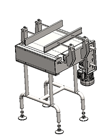
Power Roller Conveyor
-
The power roller conveyor receives the shipper from the Rotary Roller Conveyor Assembly and is continuously running to ensure smooth material flow.
-
Once the shipper is available, it is automatically conveyed forward without any start-stop delay due to continuous operation.
-
The conveyor transfers the shipper in a straight path while maintaining proper movement and spacing.
-
The shipper is then passed to the Checkweigher & Labelling Conveyor Assembly for weight verification.
14.2. Rotary Roller Conveyor operation
14.3. Maintenance
Important Precautions:
-
Read this manual carefully before operating or servicing the equipment.
-
Always disconnect power and wait at least 30 seconds before connecting or disconnecting any internal harnesses. Failure to follow this may result in serious damage or destruction of the equipment.
-
Always follow proper precautions when handling static-sensitive devices.
-
Retain this manual for future reference.
-
Do not allow untrained personnel to operate, clean, inspect, maintain, service, or tamper with this equipment.
-
Do not connect or disconnect any digital or analog components while the equipment is powered ON, as this may cause damage.
Click below to access the Maintenance Schedule for the Rotary Roller Assembly.
14.4. Risk Assessment
Risk Assessment or HAZOP, or a Hazard and Operability Study, is a systematic way to identify possible hazards in a work process. In this approach, the process is broken down into steps, and every variation in work parameters is considered for each step, to see what could go wrong.
Please refer the below attachment for HAZOP Document.
14.5. Troubleshooting
Troubleshooting is the process of identifying, diagnosing, and resolving problems or issues that arise in various systems, equipment, or processes. it involves a systematic approach to problem-solving, using a combination of analytical, technical, and problem-solving skills.
The first step in troubleshooting is to identify the problem. This can involve gathering information about the issue, including when it started, what systems or equipment are affected, and any error messages or symptoms that are observed. Once the problem is identified, the next step is to diagnose the root cause. This involves analyzing the information collected and using technical knowledge to determine what is causing the issue. After the root cause is identified, the next step is to develop a plan for resolving the issue.
Refer to the below about the Troubleshooting.
14.6 Spare List
Note: Click on the Description for details about Spare parts
3.
5.
Description
Consumables
Essential
Recomended
Sr No.
1.
2.
4.
6.
7.
8.
5
5
1
1
1
Folder Product Tray
Plastic Product Tray
AT10 Drive Belt
Metric Pulleys AT10, 32mm belt
Metric Pulleys AT10, 32mm belt
LDK TP-F 205 Hsg 4-Bolt Flange
NTN UC205-25
1
1
SIL 110 9.19ID x 14.3OD N70 O-Ring
4
Parth Magnetic Door Catch
FALSE TOOTH
AT10 Belt
Madler Keyless Coupling
Drive Pulley
Pulley Side Disc
Drive Shaft
Driven Shaft
PACKING BUSH
DOWELL
neodumium magnet N52
SILICON PAD
9.
10.
11.
12.
13.
14.
15.
16.
17.
18.
19.
20.
5
5
5
5
1
1
2
1
1
1
10
1
15.Check Weigher
15.1. 3D Model
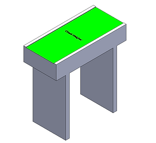
Check Weigher
-
The checkweigher receives the shipper from the Power Roller Conveyor Assembly for weight verification.
-
The shipper is conveyed over the weighing section where its weight is measured using load cell.
-
The measured weight is compared with the set value to determine whether it is OK or Not OK.
-
If the weight is OK, a signal is passed to the Labelling Conveyor Assembly to proceed further; if not OK, the shipper is rejected.
15.2. Check Weigher Conveyor operation
15.3. Maintenance
Important Precautions:
-
Read this manual carefully before operating or servicing the equipment.
-
Always disconnect power and wait at least 30 seconds before connecting or disconnecting any internal harnesses. Failure to follow this may result in serious damage or destruction of the equipment.
-
Always follow proper precautions when handling static-sensitive devices.
-
Retain this manual for future reference.
-
Do not allow untrained personnel to operate, clean, inspect, maintain, service, or tamper with this equipment.
-
Do not connect or disconnect any digital or analog components while the equipment is powered ON, as this may cause damage.
Click below to access the Maintenance Schedule for the Check Weigher Assembly.
15.4. Risk Assessment
Risk Assessment or HAZOP, or a Hazard and Operability Study, is a systematic way to identify possible hazards in a work process. In this approach, the process is broken down into steps, and every variation in work parameters is considered for each step, to see what could go wrong.
Please refer the below attachment for HAZOP Document.
15.5. Troubleshooting
Troubleshooting is the process of identifying, diagnosing, and resolving problems or issues that arise in various systems, equipment, or processes. it involves a systematic approach to problem-solving, using a combination of analytical, technical, and problem-solving skills.
The first step in troubleshooting is to identify the problem. This can involve gathering information about the issue, including when it started, what systems or equipment are affected, and any error messages or symptoms that are observed. Once the problem is identified, the next step is to diagnose the root cause. This involves analyzing the information collected and using technical knowledge to determine what is causing the issue. After the root cause is identified, the next step is to develop a plan for resolving the issue.
Refer to the below about the Troubleshooting.
15.6 Spare List
Note: Click on the Description for details about Spare parts
3.
5.
Description
Consumables
Essential
Recomended
Sr No.
1.
2.
4.
6.
7.
8.
5
5
1
1
1
Folder Product Tray
Plastic Product Tray
AT10 Drive Belt
Metric Pulleys AT10, 32mm belt
Metric Pulleys AT10, 32mm belt
LDK TP-F 205 Hsg 4-Bolt Flange
NTN UC205-25
1
1
SIL 110 9.19ID x 14.3OD N70 O-Ring
4
Parth Magnetic Door Catch
FALSE TOOTH
AT10 Belt
Madler Keyless Coupling
Drive Pulley
Pulley Side Disc
Drive Shaft
Driven Shaft
PACKING BUSH
DOWELL
neodumium magnet N52
SILICON PAD
9.
10.
11.
12.
13.
14.
15.
16.
17.
18.
19.
20.
5
5
5
5
1
1
2
1
1
1
10
1
16.Pre Label Applicator
16.1. 3D Model
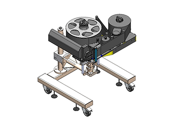
Pre Label Applicator
16.2. Pre Label Applicator operation
-
After applying tape to the shipper, it will be transferred to the labelling conveyor.
-
The label applicator applies the label to the rear corner of the shipper.
16.3. Maintenance
Important Precautions:
-
Read this manual carefully before operating or servicing the equipment.
-
Always disconnect power and wait at least 30 seconds before connecting or disconnecting any internal harnesses. Failure to follow this may result in serious damage or destruction of the equipment.
-
Always follow proper precautions when handling static-sensitive devices.
-
Retain this manual for future reference.
-
Do not allow untrained personnel to operate, clean, inspect, maintain, service, or tamper with this equipment.
-
Do not connect or disconnect any digital or analog components while the equipment is powered ON, as this may cause damage.
Click below to access the Maintenance Schedule for the Pre Label Applicator Assembly.
16.4. Risk Assessment
Risk Assessment or HAZOP, or a Hazard and Operability Study, is a systematic way to identify possible hazards in a work process. In this approach, the process is broken down into steps, and every variation in work parameters is considered for each step, to see what could go wrong.
Please refer the below attachment for HAZOP Document.
16.5. Troubleshooting
Troubleshooting is the process of identifying, diagnosing, and resolving problems or issues that arise in various systems, equipment, or processes. it involves a systematic approach to problem-solving, using a combination of analytical, technical, and problem-solving skills.
The first step in troubleshooting is to identify the problem. This can involve gathering information about the issue, including when it started, what systems or equipment are affected, and any error messages or symptoms that are observed. Once the problem is identified, the next step is to diagnose the root cause. This involves analyzing the information collected and using technical knowledge to determine what is causing the issue. After the root cause is identified, the next step is to develop a plan for resolving the issue.
Refer to the below about the Troubleshooting.
16.6 Spare List
Note: Click on the Description for details about Spare parts
3.
5.
Description
Consumables
Essential
Recomended
Sr No.
1.
2.
4.
6.
7.
8.
5
5
1
1
1
Folder Product Tray
Plastic Product Tray
AT10 Drive Belt
Metric Pulleys AT10, 32mm belt
Metric Pulleys AT10, 32mm belt
LDK TP-F 205 Hsg 4-Bolt Flange
NTN UC205-25
1
1
SIL 110 9.19ID x 14.3OD N70 O-Ring
4
Parth Magnetic Door Catch
FALSE TOOTH
AT10 Belt
Madler Keyless Coupling
Drive Pulley
Pulley Side Disc
Drive Shaft
Driven Shaft
PACKING BUSH
DOWELL
neodumium magnet N52
SILICON PAD
9.
10.
11.
12.
13.
14.
15.
16.
17.
18.
19.
20.
5
5
5
5
1
1
2
1
1
1
10
1
17.Labelling Conveyor Assembly, OCR & OVC Camera
17.1. 3D Model
-
Product Contact Parts - SS304
-
Product Non-Contact Parts - MS, RAL 7035
OCR & OVC Camera
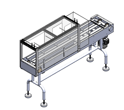
17.2. Labelling conveyor operation
-
The flat belt labelling conveyor receives the taped shipper from the checkweigher and transfers it forward for further processing.
-
When the weight from the checkweigher is OK, a signal is received and the shipper is allowed to proceed for labeling operation.
-
The pre label applicator applies a pre-printed label on the shipper, and the shipper then passes through the OCR&OVC Camera for label verification.
-
If the label is OK, the shipper is sent to the accepted pallet through the conveyor; if not OK, it is rejected to the rejection pallet using a pneumatic mechanism.
17.3. Maintenance
Important Precautions:
-
Read this manual carefully before operating or servicing the equipment.
-
Always disconnect power and wait at least 30 seconds before connecting or disconnecting any internal harnesses. Failure to follow this may result in serious damage or destruction of the equipment.
-
Always follow proper precautions when handling static-sensitive devices.
-
Retain this manual for future reference.
-
Do not allow untrained personnel to operate, clean, inspect, maintain, service, or tamper with this equipment.
-
Do not connect or disconnect any digital or analog components while the equipment is powered ON, as this may cause damage.
Click below to access the Maintenance Schedule for the Labelling Conveyor Assembly.
17.4. Risk Assessment
Risk Assessment or HAZOP, or a Hazard and Operability Study, is a systematic way to identify possible hazards in a work process. In this approach, the process is broken down into steps, and every variation in work parameters is considered for each step, to see what could go wrong.
Please refer the below attachment for HAZOP Document.
17.5. Troubleshooting
Troubleshooting is the process of identifying, diagnosing, and resolving problems or issues that arise in various systems, equipment, or processes. it involves a systematic approach to problem-solving, using a combination of analytical, technical, and problem-solving skills.
The first step in troubleshooting is to identify the problem. This can involve gathering information about the issue, including when it started, what systems or equipment are affected, and any error messages or symptoms that are observed. Once the problem is identified, the next step is to diagnose the root cause. This involves analyzing the information collected and using technical knowledge to determine what is causing the issue. After the root cause is identified, the next step is to develop a plan for resolving the issue.
Refer to the below about the Troubleshooting.
17.6 Spare List
Note: Click on the Description for details about Spare parts
3.
5.
Description
Consumables
Essential
Recomended
Sr No.
1.
2.
4.
6.
7.
8.
5
5
1
1
1
Folder Product Tray
Plastic Product Tray
AT10 Drive Belt
Metric Pulleys AT10, 32mm belt
Metric Pulleys AT10, 32mm belt
LDK TP-F 205 Hsg 4-Bolt Flange
NTN UC205-25
1
1
SIL 110 9.19ID x 14.3OD N70 O-Ring
4
Parth Magnetic Door Catch
FALSE TOOTH
AT10 Belt
Madler Keyless Coupling
Drive Pulley
Pulley Side Disc
Drive Shaft
Driven Shaft
PACKING BUSH
DOWELL
neodumium magnet N52
SILICON PAD
9.
10.
11.
12.
13.
14.
15.
16.
17.
18.
19.
20.
5
5
5
5
1
1
2
1
1
1
10
1
18.Gravity Roller Shipper Rejection Conveyor
18.1. 3D Model
-
Product Contact Parts - SS304
-
Product Non-Contact Parts - MS, RAL 7035
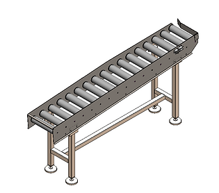
Gravity Roller Shipper Rejection Conveyor
18.2.Gravity Roller Shipper Rejction Conveyor operation
-
Rejected shippers are diverted after inspection onto the Gravity Roller Shipper Rejection Conveyor.
-
The gravity roller conveyor allows rejected shippers to move smoothly to the designated rejection collection area without powered drive assistance.
-
The assembly provides temporary accumulation of rejected shippers for operator review and removal.
-
The conveyor ensures safe and organized handling of rejected shippers without interrupting normal production flow.
18.3. Maintenance
Important Precautions:
-
Read this manual carefully before operating or servicing the equipment.
-
Always disconnect power and wait at least 30 seconds before connecting or disconnecting any internal harnesses. Failure to follow this may result in serious damage or destruction of the equipment.
-
Always follow proper precautions when handling static-sensitive devices.
-
Retain this manual for future reference.
-
Do not allow untrained personnel to operate, clean, inspect, maintain, service, or tamper with this equipment.
-
Do not connect or disconnect any digital or analog components while the equipment is powered ON, as this may cause damage.
Click below to access the Maintenance Schedule for the Gravity Roller Shipper Rejection Assembly.
18.4. Risk Assessment
Risk Assessment or HAZOP, or a Hazard and Operability Study, is a systematic way to identify possible hazards in a work process. In this approach, the process is broken down into steps, and every variation in work parameters is considered for each step, to see what could go wrong.
Please refer the below attachment for HAZOP Document.
18.5. Troubleshooting
Troubleshooting is the process of identifying, diagnosing, and resolving problems or issues that arise in various systems, equipment, or processes. it involves a systematic approach to problem-solving, using a combination of analytical, technical, and problem-solving skills.
The first step in troubleshooting is to identify the problem. This can involve gathering information about the issue, including when it started, what systems or equipment are affected, and any error messages or symptoms that are observed. Once the problem is identified, the next step is to diagnose the root cause. This involves analyzing the information collected and using technical knowledge to determine what is causing the issue. After the root cause is identified, the next step is to develop a plan for resolving the issue.
Refer to the below about the Troubleshooting.
18.6 Spare List
Note: Click on the Description for details about Spare parts
3.
5.
Description
Consumables
Essential
Recomended
Sr No.
1.
2.
4.
6.
7.
8.
5
5
1
1
1
Folder Product Tray
Plastic Product Tray
AT10 Drive Belt
Metric Pulleys AT10, 32mm belt
Metric Pulleys AT10, 32mm belt
LDK TP-F 205 Hsg 4-Bolt Flange
NTN UC205-25
1
1
SIL 110 9.19ID x 14.3OD N70 O-Ring
4
Parth Magnetic Door Catch
FALSE TOOTH
AT10 Belt
Madler Keyless Coupling
Drive Pulley
Pulley Side Disc
Drive Shaft
Driven Shaft
PACKING BUSH
DOWELL
neodumium magnet N52
SILICON PAD
9.
10.
11.
12.
13.
14.
15.
16.
17.
18.
19.
20.
5
5
5
5
1
1
2
1
1
1
10
1
19.Outfeed Conveyor
19.1. 3D Model
19.2. Outfeed Conveyor
-
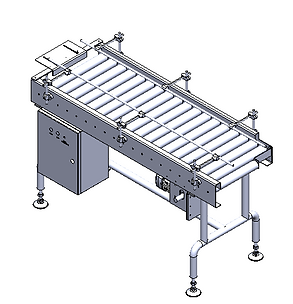
The accepted cartons are received from the OCR & Camera Inspection Assembly onto the Outfeed Conveyor Assembly.
-
The cartons are transferred continuously towards the next downstream machine/station.
-
The conveyor ensures smooth and controlled carton flow during continuous machine operation.
-
Sensor feedback is provided for carton presence detection and conveyor interlocking operation.
19.3. Maintenance
Important Precautions:
-
Read this manual carefully before operating or servicing the equipment.
-
Always disconnect power and wait at least 30 seconds before connecting or disconnecting any internal harnesses. Failure to follow this may result in serious damage or destruction of the equipment.
-
Always follow proper precautions when handling static-sensitive devices.
-
Retain this manual for future reference.
-
Do not allow untrained personnel to operate, clean, inspect, maintain, service, or tamper with this equipment.
-
Do not connect or disconnect any digital or analog components while the equipment is powered ON, as this may cause damage.
Click below to access the Maintenance Schedule for the Outfeed Conveyor Assembly.
19.4. Risk Assessment
Risk Assessment or HAZOP, or a Hazard and Operability Study, is a systematic way to identify possible hazards in a work process. In this approach, the process is broken down into steps, and every variation in work parameters is considered for each step, to see what could go wrong.
Please refer the below attachment for HAZOP Document.
19.5. Troubleshooting
Troubleshooting is the process of identifying, diagnosing, and resolving problems or issues that arise in various systems, equipment, or processes. it involves a systematic approach to problem-solving, using a combination of analytical, technical, and problem-solving skills.
The first step in troubleshooting is to identify the problem. This can involve gathering information about the issue, including when it started, what systems or equipment are affected, and any error messages or symptoms that are observed. Once the problem is identified, the next step is to diagnose the root cause. This involves analyzing the information collected and using technical knowledge to determine what is causing the issue. After the root cause is identified, the next step is to develop a plan for resolving the issue.
Refer to the below about the Troubleshooting.
19.6 Spare List
Note: Click on the Description for details about Spare parts
3.
5.
Description
Consumables
Essential
Recomended
Sr No.
1.
2.
4.
6.
7.
8.
5
5
1
1
1
Folder Product Tray
Plastic Product Tray
AT10 Drive Belt
Metric Pulleys AT10, 32mm belt
Metric Pulleys AT10, 32mm belt
LDK TP-F 205 Hsg 4-Bolt Flange
NTN UC205-25
1
1
SIL 110 9.19ID x 14.3OD N70 O-Ring
4
Parth Magnetic Door Catch
FALSE TOOTH
AT10 Belt
Madler Keyless Coupling
Drive Pulley
Pulley Side Disc
Drive Shaft
Driven Shaft
PACKING BUSH
DOWELL
neodumium magnet N52
SILICON PAD
9.
10.
11.
12.
13.
14.
15.
16.
17.
18.
19.
20.
5
5
5
5
1
1
2
1
1
1
10
1
20.Palletizer Cobot
20.1. 3D Model
20.2. Palletizer Cobot operation
-
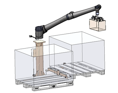
The palletizer cobot (TM25S-X Cobot) picks the shipper from the palletizer Lable conveyor based on accepted and rejected signals.
-
The cobot palletizes the shipper according to the predefined pattern for accepted and rejected flow.
-
The cobot has a pneumatically operated pick head for handling the shipper during pick-and-place operation.
-
The pallet is placed manually and the cobot performs automatic palletizing operation.
20.3. Maintenance
Important Precautions:
-
Read this manual carefully before operating or servicing the equipment.
-
Always disconnect power and wait at least 30 seconds before connecting or disconnecting any internal harnesses. Failure to follow this may result in serious damage or destruction of the equipment.
-
Always follow proper precautions when handling static-sensitive devices.
-
Retain this manual for future reference.
-
Do not allow untrained personnel to operate, clean, inspect, maintain, service, or tamper with this equipment.
-
Do not connect or disconnect any digital or analog components while the equipment is powered ON, as this may cause damage.
Click below to access the Maintenance Schedule for the Pallertizer Cobot Assembly.
20.4. Risk Assessment
Risk Assessment or HAZOP, or a Hazard and Operability Study, is a systematic way to identify possible hazards in a work process. In this approach, the process is broken down into steps, and every variation in work parameters is considered for each step, to see what could go wrong.
Please refer the below attachment for HAZOP Document.
20.5. Troubleshooting
Troubleshooting is the process of identifying, diagnosing, and resolving problems or issues that arise in various systems, equipment, or processes. it involves a systematic approach to problem-solving, using a combination of analytical, technical, and problem-solving skills.
The first step in troubleshooting is to identify the problem. This can involve gathering information about the issue, including when it started, what systems or equipment are affected, and any error messages or symptoms that are observed. Once the problem is identified, the next step is to diagnose the root cause. This involves analyzing the information collected and using technical knowledge to determine what is causing the issue. After the root cause is identified, the next step is to develop a plan for resolving the issue.
Refer to the below about the Troubleshooting.
20.6 Spare List
Note: Click on the Description for details about Spare parts
3.
5.
Description
Consumables
Essential
Recomended
Sr No.
1.
2.
4.
6.
7.
8.
5
5
1
1
1
Folder Product Tray
Plastic Product Tray
AT10 Drive Belt
Metric Pulleys AT10, 32mm belt
Metric Pulleys AT10, 32mm belt
LDK TP-F 205 Hsg 4-Bolt Flange
NTN UC205-25
1
1
SIL 110 9.19ID x 14.3OD N70 O-Ring
4
Parth Magnetic Door Catch
FALSE TOOTH
AT10 Belt
Madler Keyless Coupling
Drive Pulley
Pulley Side Disc
Drive Shaft
Driven Shaft
PACKING BUSH
DOWELL
neodumium magnet N52
SILICON PAD
9.
10.
11.
12.
13.
14.
15.
16.
17.
18.
19.
20.
5
5
5
5
1
1
2
1
1
1
10
1
21.Pallet Locator
21.1. 3D Model
Main Structure - MS, RAL 7035
Pallet Locator
21.2. Pallet Locator operation
-
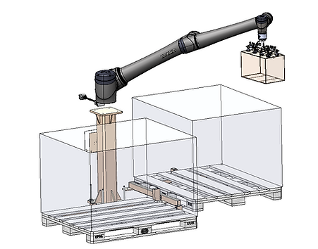
Pallet Locator helps to load pallets at the correct location. Pallet locator has photoelectric sensors to detect pallet presence or absence.
22. Guards Assembly
22.1. 3D Model
22.2 Guard Assembly Operation
-
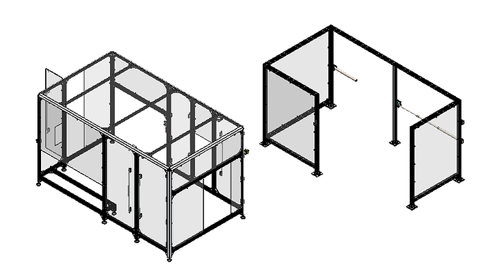
The guard assembly ensures the safety of personnel during the operation of the machine